In this first video after the system was built, you see the unmodified code in action. I was extremely excited at this point, so I wasn't really paying to much mind for the eficacy of the system, just that it worked!
In this next clip, I have changed up the code slightly, yeilding positive results. Comments are made about this through captions on the video.
At this point I decided it was important to get something to diffuse the light source, as it was pretty intense as direct light. I also thought about putting it behind some of my acoustic treatment, however that would have taken time I do not have.
this is part of a pair of two, the second of which is housing the LEDs. this is being used as the lid for the plate that holds the electronic circuit that connects the Arduino to the LED strip.
Fortunately, the Breadboards come with 3M sticky pads on the back, so mounting them in was easy. However this needed holes to allow connection via USB for future development and also for power input. I havent yet done the LED hole, however that wil be done for the Expo.
A quick snap of the holes... The one with a cable attached is the power lead, whilst the open one is for the USB. As you can also see, the glass is all fuzzy now... This is my homemade version of light diffusion using tracing paper...
And there it is in all it's glory. Here is a more in depth explanation of light diffusion if you aren't familiar with the concept.
Closer to the expo, I shall replace my tracing paper system with this sort of film to make it look extra plush, however this is suitable for testing in the mean time.
The following videos were actually shot before the mounting plate was fixed, so the electronics are down by the side, however the functionality is exactly the same - none of the code is being changed anymore, as is explained through the following videos.
Explaining the diffusion and EQ band distribution.
Here you see it with the delay time reduced, this yeilded a better result for using this a metering tool and not just a cool light.
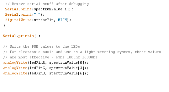
There is how I changed the code, along with explanations for people using this in the future. in the instance above, this is to irradicate extra chaff from the MSGEQ7. Even if it has no audio input, when on it outputs value between 45-85, meaning you have to fliter off any value below 90 to be sure you get no interference in the LED strip.
Next, the MSGEQ7 read values are changed from 1, 4 and 6 to 0, 3 and 6. After testing between the two, I found there was a marked improvement for modern audio material when these EQ bands were selected. In case you are wondering, 0 is the first value. Very often, couter intuative things like this are seen in electronics... At first I had no idea 0 could be used and assumed 1 was the lowest EQ value. Only when I tried to send blue 7's data did I realise that 7 didnt exist. I put 2 and 2 together and tried 0 as Red and it worked. the moral of the story is experiment!
You see the final code in action, yeilding far more accurate and tight results. this is because I have now changed the delay time for bumping the strobe to a lower value than the original code.
At first I thought making it slower made sense, but I wasnt thinking about the refresh rate that our eyes work at. I needed to achieve a minimum of 25 frames a second to make it appear smoother, I acheived this by making the delay time 25ms. this actually give us a theoretical frame rate of 40 fsp. I feel the results speak for themselves.
Now here are a couple more before I started using the system as a studio tool.
And a full tune with the system above the diffuser in it's rightful new home!
I am really happy with the way it works if Im honest. It s now like sitting in a nightclub without having to actually do anything to make it happen than turn up the second output on my soundcard. I'm in love.


No comments:
Post a Comment