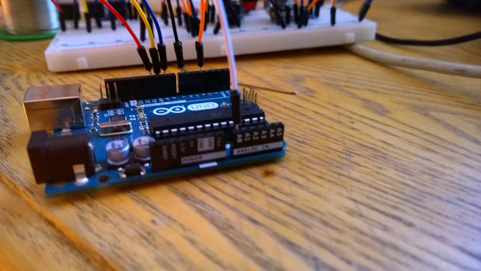
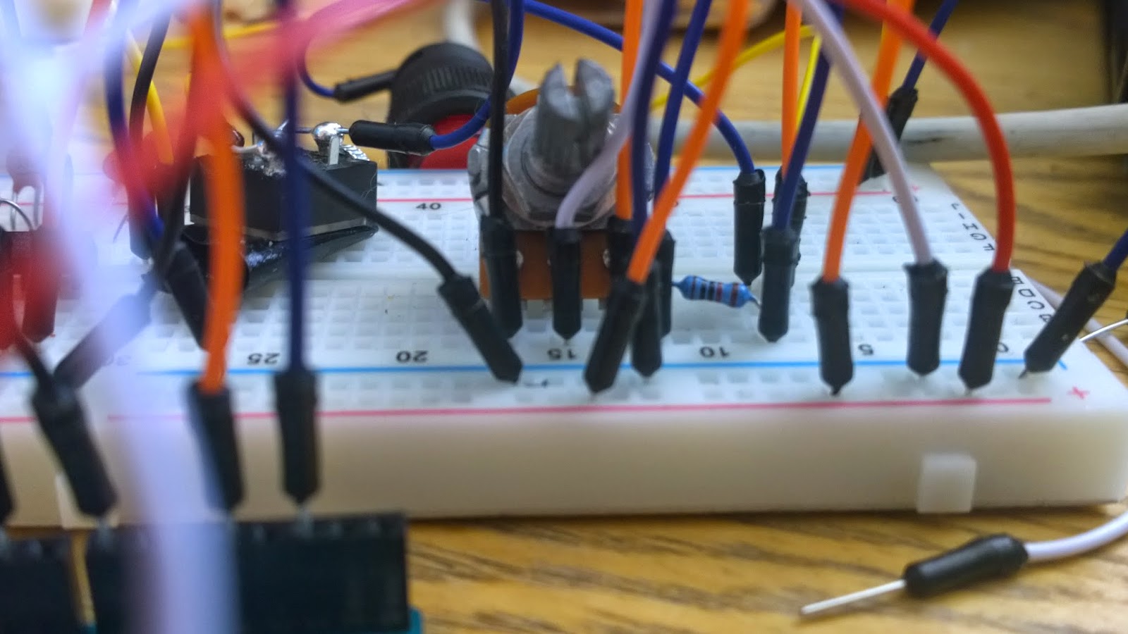
1) Here you see Digital Pins 9, 10 and 11 from the arduino connected to the Gate Pins of each of the N Channel MOSFETs. You also see Pin 7 occupied, it is connected to the Reset Pin 7 of the MSGEQ7.
2) Next digital Pin 4 of the arduino is connected to Strobe Pin 4 of the MSGEQ7 (orange wire). Digital Pin 2 of the arduino is connected just underneath the 10K resistor (blue wire).
4) Here are the red and white cables seen above connected to the breadboard.
5) Next we have the yellow Vin connected to the top positive rail.
6) Now we look at the analogue inputs of the arduino. Connect analogue pin 1 (A0) to the central pin of the 1K potentiometer.
7) Next, analogue in pin 4 (A3) is connected to the output pin 3 of the MSGEQ7.
8) Finally, I have jumper inserted into the RGB and 12v inputs of the LED strip ready for connection. The RGB lines will be connected to the Drain pins of the N Channel MOSFETs from left to right respectively, and 12v is fed from the 12v power line.
So the arduino code is loaded, the Breadboard and circuitry is complete to the fritzing guide. Hopefully this rebuild may yield some results! Fingers crossed :) One final point for Russell, I decided it would be easier to follow his method of powering it all, and found a similar power brick to the one that came with the LEDs (except I havent stripped the connection off this one). I see no reason why it wont work, it's the same voltage with a slightly lower amperage. Hopefully this should be OK.
The Left one is the original LED PSU, the right one is the one im using.


This comment has been removed by the author.
ReplyDeleteUnless you plan on cutting the strip down and using a smaller portion than the full 5m, use the 5A supply. At full brightness on all three colors, that strip can pull as much as 1A per meter, and that's not factoring in the draw from the Arduino or MSGEQ7. Granted, you probably won't be running it at full white a whole lot, but it's always better to have a supply that can provide more amperage than you need.
ReplyDelete