Showing posts with label Arduino. Show all posts

Saturday, 25 April 2015

Final Artefacts Demos and Explanations Part 2

I first have to say that formal testing of the system in terms of using it whilst working on music was impossible with my current setup - I dont have two computers. However at the expo I have access to another computer loaded up with music software, so it will be possible to demo the systems together in that capacity.

For these examples, I have run the two systems together as colour organs in order to demo and analyse the efficacy of the systems.

While I am waiting for the videos to upload to Youtube, here is a quick phoo to get the idea and allow me to keep typing!


Before I go on, I want to talk about some of the immediate issues I noticed with te system, that perhaps you too have noticed.

I really hadn't considered the fact that one light source cast on to such a surface would cast shadows onto shorter pillars that were off center. When far enough back, you can hit all the longest pillars easily, however the deeper the other pillars are by relation to the longest, the more extreme the shadows cast become.

There is a way round this, however there is only one - to have multiple projector rigs. this is expensive, space consuming, time consuming and noisey. Realistically, for use as a tool for analyitical insight into audio in the studio, it doesn't have much future. This is certainly not to say that it hasn't been extremely insightful as a method for analysing the light speaker though. It has also been a gret way for exploring the power of FFT analysis for splitting up incoming audio rather than traditional filter based EQ's in the analogue domain, such as the MSGEQ7

At this point the diffuser is unpainted as I relly dont have the time, so there is a very slight tinge of orange to the colour, as seen in the above picture. the colour being shown on the acoustic diffuser then should match the laptop screen, which is extremely similar to what the colour organ above is displaying - a kinda of pinky off white tone. As a note, this means there was a pretty even balance of audio frequencies at that point in time, with a slight tendency towards the lows and highs. Turns out that you can gain meaningful insight into audio from colour ;)

The first of the demo videos of these two in action are taking a while to upload, so for now Im going to get on with seting up my Ableton set ready for testing later on this evening on the flatmates.

I have decided that I'm going to be asking them to listen to a bunch of material chosen by them first, then me, in order to get used to the systems first. During this time, I will be going over a bit of basic colour theory with them to make sure they can understand just what is going on. Once this is done, I am going to go through a set bunch of material such as drum loops and musical stems to demonstrate what certain types of sounds look like, I am then going to ask them to indentify what they are listening to without the speakers, using only the light. If they can determine what they are listening to, roughly at least, without listening, then I would say the system has real legs as a tool for metering audio in a creative manner.

I shall also do an intermediate piece about how a made the colour organ within Resolume. Cheers!


Thursday, 2 April 2015

Problems with the Circuit Part 2

So to continue from my last post, here is a photo diary of me connecting the arduino to the breadboard.

1) Here you see Digital Pins 9, 10 and 11 from the arduino connected to the Gate Pins of each of the N Channel MOSFETs. You also see Pin 7 occupied, it is connected to the Reset Pin 7 of the MSGEQ7.

  
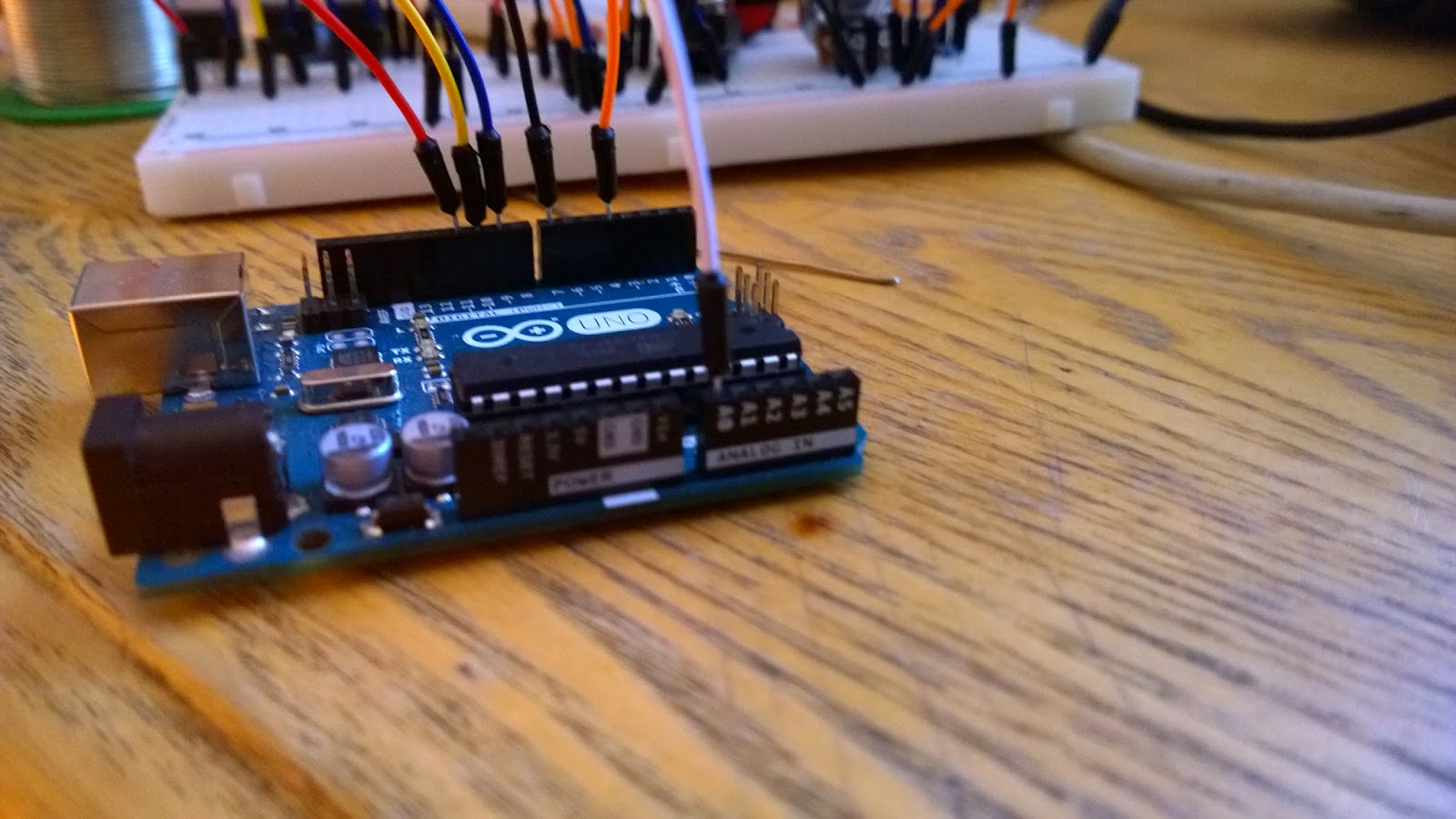
2) Next digital Pin 4 of the arduino is connected to Strobe Pin 4 of the MSGEQ7 (orange wire). Digital Pin 2 of the arduino is connected just underneath the 10K resistor (blue wire).

 3) Here we are connecting the power connections from the arduino to the board. Take the 5v output of the Arduino and connect it to the bottom positive power rail. The ground pin next to the 5v and connect it to the bottom ground rail. Then take the Vin pin on the arduino and connect it to the top positive power rail.


4) Here are the red and white cables seen above connected to the breadboard.


5) Next we have the yellow Vin connected to the top positive rail.


6) Now we look at the analogue inputs of the arduino. Connect analogue pin 1 (A0) to the central pin of the 1K potentiometer.


7) Next, analogue in pin 4 (A3) is connected to the output pin 3 of the MSGEQ7.


8) Finally, I have jumper inserted into the RGB and 12v inputs of the LED strip ready for connection. The RGB lines will be connected to the Drain pins of the N Channel MOSFETs from left to right respectively, and 12v is fed from the 12v power line.


So the arduino code is loaded, the Breadboard and circuitry is complete to the fritzing guide. Hopefully this rebuild may yield some results! Fingers crossed :) One final point for Russell, I decided it would be easier to follow his method of powering it all, and found a similar power brick to the one that came with the LEDs (except I havent stripped the connection off this one). I see no reason why it wont work, it's the same voltage with a slightly lower amperage. Hopefully this should be OK.


The Left one is the original LED PSU, the right one is the one im using.


Wednesday, 1 April 2015

Problems with my Audio Reactive LED circuit

So I finally got all the last parts for the project and set about building the circuit last night with no success, so I have decided to give a photo blog of the build stage by stage for the benefit of Russell who can hopefully point out to me where I have gone wrong.

This is going to be snappy as I have lots to do and don't want to bore Russell. So from the top then!

1) Insert MSGEQ7


2) Connect Caps (Left 33pf, right 100nf). The left wire of thee right cap goes to Ground Pin 6 of the MSGEQ7. The 33pf's right wire connects to Oscillator Pin 8 (connection will be broken with resistor)


3) Connect 3rd Cap, which sits "over" the second cap. The left wire goes to Input Pin 5


4) Insert 220K resistor between 33pf and Pin 8


 5) Insert second 100nf cap. Pin 1 Positive and Pin 2 Negative


 6) Connect Positive and Negative Pins to the power rail via Cap.


7) Next is soldiering two jump wires the positive and ground connection on this little Stereo Jack Input.


8) You see 5 Pins, Ground is the centre pin, closest to the input. The two at the top here (actually on the right) are Negative, and the bottom two are positive. TRS stands for Tip, Ring, Sleeve. Tip is positive, Ring is Negative and Sleeve is ground.


9) Here is the Input with jumpers soldiered on. (And a slightly burnt desk :/)


10) Here is the TRS taped down to the BB with leccy tape. The positive connects through Cap 2 to Input Pin 5, Ground to the Ground Rail.


11) 3 N Channel MOSFET Transistors are added to the board. N Channels have three pins, Gate, Drain and Source from left to right.


 12) Each source Pin is connected to the ground top rail of the breadboard.


13) The 220k resistor is now connected to the bottom power rail - live to left, ground to right.


14) Here is another angle to show the exact connection, the ground wire connects to the 33pf capacitor left wire, not the resistor.


15) Here we connect the ground of the MSGEQ7 to the bottom ground rail.


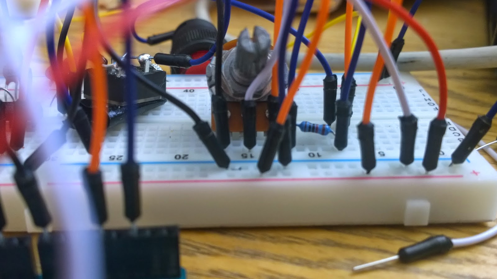
16) Next I insert the 1K potentionmeter and 10K resistor. They are not connected.


17) Here, the ground rails are connected together, a button is attached via soldiered jump wires. The live rail is connected to the positive of the button, the negative back to above the 10K resistor. I have also attached the bottom live rail to the right pin of the potentiometer.


18) Here, I attach a jumper to the central pin of the potentiometer for data transfer to the arduino, I have also connected the jumper from the left of the 10K resistor to the bottom ground rail.


19) Here the left pin of the potentiometer is connected to the bottom ground rail.


20) Here are the connections for the arduino attached to the gate pins of the MOSFETs


21) Finally, I attach the live 12v top rail connector which feeds the LED strip power.


So as far as I am aware, that should be the breadboard and circuit good to go, next post is about all the connections from the Arduino to the Breadboard, there will be a tutorial just like this for that too. Hopefully these can go towards helping people do this in the future too! Cheers

Saturday, 28 March 2015

Project Explained Part 1 - Arduino, MSGEQ7 and Audio to Colour Theory and Practice

I have had tons of stuff going on recently with the project, so today is going to be a catch us on the written side of it all.

First off I feel like I should give you an update on some of the difficulties that I had been having with the LED side of the project. Firstly, once again I am no electrician and this is all new to me, I have done a lot of reading trying to get my head around electronics and I think I have a stronger idea, but to say I fully understand it would be an exaggeration.

Also, without the code and guidance from a man named Russell, who has been helping via online chat through Blogger and Youtube, I certainly wouldn't have achieved this. He will be credited as such in my dissertation.

I have also had difficulty in getting parts. Well, more the time scales that they come. I completely underestimated how long it would take for some things to arrive, my longer breadboard took 5 weeks!!

I am now nearly there though, all I need to get my hands on is a female TRS Jack input for the audio in, and a 10K resistor, though I may just be able to use one of the 220k ones I already have for that purpose. I also need to soldier the button I got into place, as it is not very Breadboard friendly.

Also my ignorance in implementing the code into the Arduino was also holding me back. I have since figured out what it was that I was doing wrong, so now the Arduino is loaded with the code it needs. By the end of this coming week I should have a working audio-reactive acoustic diffuser. I think it may be the first one in the world! Wouldn't that be exciting. The next post today after this shall be dedicated to the Diffuser build and where that is at, but for now its all LED.

So first off, here is an overview of what is going on. Compared to my last post about Arduino control of LED's, you can see the Breadboard that I waited five weeks for is in place. Damn I wish China wasn't so far away. And amazong was more obvious where you were buying from :( Aaaaanyway.


So rather than using the power brick plugged into the Arduino, I am just using the stripped ends of the 12v power brick that came with the LED strip. Hopefully Russell can confirm wether this will work or not, if not then I know how to connect it up his way too, that's fine.


Next we have the potentiometer circuit. Once the board is fully equip with the button, this circuit will allow the user to cycle through the 8 states contained within the code. One button click cycles through these states, where the potentiometer controls the intensity of each program.


 The next circuit is doing the hard graft. Above the middle of the Breadboard, you can see 3 capcitors - 33pf, 0.1uf and 0.01uf (Left to Right). You may have already noticed that the two on the right are twisted together. I shall get some clarification exactly why that is, but I think it is to with stepping the signal down from the audio input, which will be connected this week.


Sticking with the image above, I shall explain what the little black box straddling the middle of the breadboard is. It is called the MSGEQ7 and it is really the brains of the operation here. It is a seven band audio splitter - it splits incoming audio into 7 separate frequency bands from Low to High frequencies.
Below is a small snippet of the Datasheet for the MSGEQ7. It shows the most important signal flow diagrams though. You can also see the specific band passed frequencies it outputs information for.

 
So here you can see a physical diagram and block electrical diagram of the chip (Top Right). If you imagine twisting that diagram round 90 degrees to the left, you have the orientation of the chip on the breadboard. So as I said before, the audio signal comes in through the top right pin, Pin5 (in that orientation). One left, we have the Ground Pin6, nothing to interesting. Next, Pin7 resets the multiplexer operation, on the board this is connected . Pin8 controls the chips onboard oscillator, which is responsible for selecting the frequency of the multiplexor, or how fast the strobe cycles through the audio frequency bands. When the input of Pin8 is high, the multiplexor is reset. When the signal goes low again it enables the Strobe Pin4, which is on the lower side of the chip. Pin3 is the Output, which is the Multiplexed signal. This is connected to the fourth analogue input on the arduino (A3) which unfortunately I forgot to wire up for the picture, but is now in place. Pin1 and Pin2 are the positive and negative power inputs for the chip, the power for which is controlled by the second 0.1uf capacitor.

Next we have the third stage of the Board, which is controlling the LED's. So trying to keep it basic, as I said before the MSGEQ7 spits out a multiplexed output, which means a stream of repeating data. That stream of data contains the volume information for each of the 7 frequency bands that the MSGEQ7 split the audio into.

What we need to do then is convert that data into RGB data which can be turned into coloured light that represents frequency via the LED strip. This is the part of the process that the Arduino takes care of.

If you have read my earlier work on this project, you will know that light and sound are inherently tied together, and one octave of the musical scale (F# through to F#, 370hz - 740hz) can be exactly converted to the octave of the visible light spectrum (Deep Magenta/Red through to Dark Blue/Purple, 406.8ghz - 813.6ghz). To get the exact colour to tone, you multiply the audio frequency by 2 to the power 40. Now we have some context for what I say next.

There are (very basically) three levels of colour. These are known as the Primary, Secondary and Tertiary Colours. The primary colours are out basic building blocks - with them, we can make Secondary and the Tertiary colours. Our primary colours are RGB, Red, Green and Blue. When we combine these together, we can (just about) make any colour in the rainbow. For example, if I wanted to create the colour Yellow from light, I would mix together equal amounts of Red and Green light. It is vastly more complex than this, but an easy way to think of it is how beat frequencies work, it's a form of frequency modulation.You can demonstrate this to yourself by use of some simple maths, though some of you have no doubt got it by now... If you take average between any to colour frequencies, you will get another colour.


Basically, if send varying R,G&B voltage amounts to the LED strip, then we will get a colour representation of the full audio frequency spectrum. Bass shall be represented by pure red, the Mids by green and the Highs by Blue. This can obviously be changed quite easily in the code, but for now it shall be remaining the same as I want to test this as a metering source. The three black things you see sticking out the breadboad are N-Channel Mosfets. They are special resistors that you can think of as Envelope Followers and are what control the flow of Red Green and Blue signal to each channel of the LED strip. It smoothing basically.

In the picture below I am holding that yellow cable for the benefit of Russell, hopefully he can tell me whether or not I can get away with powering the LED strip this way. You can see from earlier pictures that the Power Brick was plugged into the top rail of the Breadboard. I think this way I can avoid having to get a power brick with a proper connection, as I chopped the last one off for the last arduino project.


 Finally we have a picture of it all together. The code is on the Arduino, so hopefully once I have the TRS and button attached I should be plain sailing! The next post is going to be in a while after I have had a break. Once it is composed, I might just leave till tomo morn to post as I will most likely be very tired!