I thought at this point I should show off one of the pieces I have made while using my Light Speaker in the studio. One thing I noticed about using it was it strongly encourages anybody using it to keep dynamics in their track and not go wild.
I dont have time to upload, but when playing Skrillex tracks, which are known to be among the loudest printed audio ever commercially released, basically the system just displays white, because all frequency bands are pushed so hard against the ceiling, even when a kick plays, there is lots of high end activity.
There has been a massive push back against this "loudness war" within the music industry. I strongly believe that with refinement, the Light Speaker could be used as a way of encouraging producers to stay away from their limiters, as it shows in a very visual manner the damage that over squashing does to audio.
During mixing, the light speaker should be dynamically shifting through colours, displaying the full rainbow. If you start to see the overall balance shifting towards white, then you are overcooking your mix and have to back of on your levels.
I think this is a very intuative and fun way of keeping an eye on what you are doing in terms of mixing audio and keeping clarity in your mix. Lot's of colour - GOOD. Lot's of white - BAD. Thats pretty easy to understand, right?
So as one of my final videos showing the Projection Mapping system in action, here is a tune I wrote using the Light Speaker as reference throughout.
As you can see, there is plenty of colour shifting, meaning the mix has not been overcooked. I found the process of writing with it genuinely insightful and fun. Even if no one else in the world finds a use for this, I certainly will, so in that respect it has been a resounding success.
In the accompanying portfolio there are many more video's of the two systems combined, including another piece I wrote using the Light Speaker called "Nightmares in the Light".
So earlier in the project I talked about generative graphics as well. In terms of teh final proect this has become less relevant, however I still want to demonstrate some of the work I put into the development of the idea.
Though the colour organ in Resolume was made using FFGL generative graphics, there are a range of other patches and parameters that can be manipulated by an audio signal. this could be much more useful for live performance and making fully integrated audio visual set's for me to perform, something that I will definitely be doing a lot more of again after uni!
Here is a video of me running a piece from Australian artist Mr Bill through the system. Many more examples of this will be demo'd at the expo.
Again, this would be far to distracting to be used in the creation process, but as I said for live performance as an artist this is an amazing platform for development. for instance, I could create a live set with the system in action, then bring the same system along to any live performance I do and have the same visuals in the venue I am playing at.
It has also been useful for imagining other methods for achieve an effect like this. For instance, I would like to investigate the possibility of developing a clear acoustic diffuser that is loaded with small LED screens, or simple LEDs. This could be incredible and haave all the ease of setup as the light speaker, with the visual effect of the Projection Mapping system.
So now we move deeper in to the Projection Mapping aspect of my project. As I have talked about already, for the remainder of testing the system isn't practical enough and I don't have two computers.
In order to compare the efficacy of each system as "monitoring" for audio signals, I decided that the best thing to do would be to run them both in tandem and determine through my own practice which system (FFT or Analogue Filtering) is the better. For clarification once again, Resolume uses FFT analysis of audio and allows you to select a range of 32 bands of signal, to control the parameters within the software and 3rd party plugins.
Once again I am waiting for videos to upload, so in the mean time here are some stills of the full system working together. As you can see, there is actually quite a synergy between the two systems.
Above are six still shots taken of the systems combined. As you cans see, there seems to be a pretty constant correlation between the two systems.
It might not seem obvious at first, but essentially I am concerned with how easily colour can be generated from audio and then how easily we can interpret that information.
I have talked about this before, but I find metering an extremely boring process, yet extremely neccessary for getting a mix right. I have also always wanted an outboard metering source, as I hate having to either put spectrum analyser on every channel, or on the master of my DAW.
In both cases, I have to click to view it, because of this, my creative process gets broken. This is no good; I want to be creating, but the technical side of my brain likes to eliminate mix problems as they arise. Outboard metering solves that issue. It doesn't solve the boring aspect however.
That's where my idea for this whole project comes from, so it is pretty encouraging that colour can reliably represent sound in this manner. That isn't to say they aren't without their issues, however as a starting point for development of a commercial audio metering system, these results are encouraging.
As with anything technical, there is a learning curve. I would argue that in the case of system a kin to the one above, this learning curve would be extremely fun.
Having tested the systems together at length, I now know the Arduino powered light speaker is the system that has legs as an audio metering source for the masses.
The resolume FFT analysis system is unquestionably more powerful, however it has too many constraining factors surrounding it's implementation for it to ever be practical as a product for sale. Thanks to student discount I have the software, but supposing the user wasn't in education, this system would cost over 1000 pounds to implement, making it out of reach for most people.
In terms of detail of analysis, both systems work well, however I would say that the FFT powered system performs better through the representation of the Mid Range audio to colour conversion, so it's definition through the Orange, Yellow and Lime Green range (200-600hz) is greater. It is also smoother when changing colour spectra. One of the main weakness that I hadn't considered is that the projector is always casting a light on whatever it is pointed at. In that respect, it actually fails my list of essential parameters outlined in the dissertation and there is literally no way around that. I am going to continue though as it is worth noting the differences.
Through this is more pleasing, it is actually not as good for analytical insight into the signal. It is also visually pleasing to the point of distraction. I have been working a lot with the light speaker and now it has completely integrated into my workflow. I can't see integrating as much, it is extremely cool for parties and I prefer this sort of visual than some half cut VJ putting up youtube rips of transformers or some bullshit, but I feel like I would spend more time looking at it than producing if it was an easily integratable system. Which it isn't
Anyways, here is the first video showing this system in action.
It's going to take a while to get the next few vid's uploaded, so Ill leave this post here and get ready for testing the Light Speaker in a more formal manner.
So the video has finally uploaded, here is a full tune run through the first iteration of the mapping system, run in tandem with the Arduino Powered light speaker.
As I discussed in the last post showing this system, there are obvious issues with the fact that having only 1 projector cause many shadows to get cast on shorter posts. I do still think the overall effect is very cool. For testing it to begin with, I didnt set the projector as far back as I could have, so I didnt take to long long mapping, I only did a few posts as you can see. I do still think its a very cool thing to look at, but it's not quite how I had imagined it, as happened with the Light Speaker.
In the next post, we will get deeper into Resolume and the mapping system, it's pro's and con's and how accurate it is by comparison to the analogue equivalent, my Arduino light speaker.
Bit behind due to the fact I managed to delete the last post like a total spanner. ANYWAYS #dafttwat
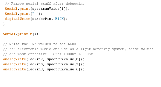
Digging deeper into the Arduino code I showed a bit of in the last post, I want to talk about each section of the code and how it effects the system.
Here you see two sections of code, aspects of which will be familiar to anyone who uses Arduino. The first thing that you always have to do with any Arduino project is define your pins (that is unless you are doing pure maths equations, geek). We do this by using the "int" prompt, and then the corresponding name we want to give the pin, followed by "Pin" = "Corresponding Pin Number".An example of this would be...
int ledPinR = 9;
Next, we have the void setup. This area of Arduino code controls the starting conditions for any patch. We use a serial input res of 9600.
As the Arduino has both Analogue Inputs and Outputs, we have to define which of the MSGEQ7's in's and out's go to the Arduino.
In order to ping the MSGEQ7 we also have to set the digitalWrite values in either Low or High states. As described by J Skoba and talked about earlier in the blog, we strobe the MSGEQ7 by seting our digitalWrite value High.
So to start the code off, we need the value Low (resetPin), as we want it to strobe when it first detects a signal when run. The reference voltage is also set at 5V, native to the arduino and enough to run the circuit.
The next section of code, which again will be familiar to Arduino Geeks, is the "Void Loop". Essentially this is a block of code that repeats indefinitely, in order to run your program.
As you can see, the first thing we do is set the strobePin value to High, and resetPin Low.
Next, we define the number of values we are looking for after the strobe is bounced. In this case, that is the 7 values of the MSGEQ7. Then, we have to define what the delay time is until the next strobe is bounced. As I have already talked about, this is now set to 25ms.
Then, we take the read rfom the analogue input pin of the Arduino, which is taking the feed from the MSGEQ7.
Next, we need to constrain this value. As discussed before, this value that comes in from the MSGEQ7, runs upto 1023 per band. In order to make it compatible with the colour theory discussed in the disertation and how LED voltages work, we need to constrain this value to within a range of 0-255 per band.
We do this using the "map" and "constrain" functions of Arduino coding. As you can see above, it is pretty simple to understand. We use these in combination to remap values that fall in between one range, into values that fall between a range either larger or smaller than the original.
All we need to do is then define which band of data we have analysed, constrained and remapped, to send to which LED colour. In this case we go RGB from Low to High, so band [0] - 63hz goes to Red, band [3] - 1000hz goes to Green and band [6] - 16000hz goes to Blue.
And that is that. We we apply colour theory in this practical manner, it turns out we dont need very complex FFT to generate every colour of the rainbow!
In this first video after the system was built, you see the unmodified code in action. I was extremely excited at this point, so I wasn't really paying to much mind for the eficacy of the system, just that it worked!
In this next clip, I have changed up the code slightly, yeilding positive results. Comments are made about this through captions on the video.
At this point I decided it was important to get something to diffuse the light source, as it was pretty intense as direct light. I also thought about putting it behind some of my acoustic treatment, however that would have taken time I do not have.
this is part of a pair of two, the second of which is housing the LEDs. this is being used as the lid for the plate that holds the electronic circuit that connects the Arduino to the LED strip.
Fortunately, the Breadboards come with 3M sticky pads on the back, so mounting them in was easy. However this needed holes to allow connection via USB for future development and also for power input. I havent yet done the LED hole, however that wil be done for the Expo.
A quick snap of the holes... The one with a cable attached is the power lead, whilst the open one is for the USB. As you can also see, the glass is all fuzzy now... This is my homemade version of light diffusion using tracing paper...
And there it is in all it's glory. Here is a more in depth explanation of light diffusion if you aren't familiar with the concept.
Closer to the expo, I shall replace my tracing paper system with this sort of film to make it look extra plush, however this is suitable for testing in the mean time.
The following videos were actually shot before the mounting plate was fixed, so the electronics are down by the side, however the functionality is exactly the same - none of the code is being changed anymore, as is explained through the following videos.
Explaining the diffusion and EQ band distribution.
Here you see it with the delay time reduced, this yeilded a better result for using this a metering tool and not just a cool light.
There is how I changed the code, along with explanations for people using this in the future. in the instance above, this is to irradicate extra chaff from the MSGEQ7. Even if it has no audio input, when on it outputs value between 45-85, meaning you have to fliter off any value below 90 to be sure you get no interference in the LED strip.
Next, the MSGEQ7 read values are changed from 1, 4 and 6 to 0, 3 and 6. After testing between the two, I found there was a marked improvement for modern audio material when these EQ bands were selected. In case you are wondering, 0 is the first value. Very often, couter intuative things like this are seen in electronics... At first I had no idea 0 could be used and assumed 1 was the lowest EQ value. Only when I tried to send blue 7's data did I realise that 7 didnt exist. I put 2 and 2 together and tried 0 as Red and it worked. the moral of the story is experiment!
You see the final code in action, yeilding far more accurate and tight results. this is because I have now changed the delay time for bumping the strobe to a lower value than the original code.
At first I thought making it slower made sense, but I wasnt thinking about the refresh rate that our eyes work at. I needed to achieve a minimum of 25 frames a second to make it appear smoother, I acheived this by making the delay time 25ms. this actually give us a theoretical frame rate of 40 fsp. I feel the results speak for themselves.
Now here are a couple more before I started using the system as a studio tool.
And a full tune with the system above the diffuser in it's rightful new home!
I am really happy with the way it works if Im honest. It s now like sitting in a nightclub without having to actually do anything to make it happen than turn up the second output on my soundcard. I'm in love.
I first have to say that formal testing of the system in terms of using it whilst working on music was impossible with my current setup - I dont have two computers. However at the expo I have access to another computer loaded up with music software, so it will be possible to demo the systems together in that capacity.
For these examples, I have run the two systems together as colour organs in order to demo and analyse the efficacy of the systems.
While I am waiting for the videos to upload to Youtube, here is a quick phoo to get the idea and allow me to keep typing!
Before I go on, I want to talk about some of the immediate issues I noticed with te system, that perhaps you too have noticed.
I really hadn't considered the fact that one light source cast on to such a surface would cast shadows onto shorter pillars that were off center. When far enough back, you can hit all the longest pillars easily, however the deeper the other pillars are by relation to the longest, the more extreme the shadows cast become.
There is a way round this, however there is only one - to have multiple projector rigs. this is expensive, space consuming, time consuming and noisey. Realistically, for use as a tool for analyitical insight into audio in the studio, it doesn't have much future. This is certainly not to say that it hasn't been extremely insightful as a method for analysing the light speaker though. It has also been a gret way for exploring the power of FFT analysis for splitting up incoming audio rather than traditional filter based EQ's in the analogue domain, such as the MSGEQ7
At this point the diffuser is unpainted as I relly dont have the time, so there is a very slight tinge of orange to the colour, as seen in the above picture. the colour being shown on the acoustic diffuser then should match the laptop screen, which is extremely similar to what the colour organ above is displaying - a kinda of pinky off white tone. As a note, this means there was a pretty even balance of audio frequencies at that point in time, with a slight tendency towards the lows and highs. Turns out that you can gain meaningful insight into audio from colour ;)
The first of the demo videos of these two in action are taking a while to upload, so for now Im going to get on with seting up my Ableton set ready for testing later on this evening on the flatmates.
I have decided that I'm going to be asking them to listen to a bunch of material chosen by them first, then me, in order to get used to the systems first. During this time, I will be going over a bit of basic colour theory with them to make sure they can understand just what is going on. Once this is done, I am going to go through a set bunch of material such as drum loops and musical stems to demonstrate what certain types of sounds look like, I am then going to ask them to indentify what they are listening to without the speakers, using only the light. If they can determine what they are listening to, roughly at least, without listening, then I would say the system has real legs as a tool for metering audio in a creative manner.
I shall also do an intermediate piece about how a made the colour organ within Resolume. Cheers!